Building up a battery assembly lab, part 2
In part 1, I described which tools are needed for building coin cells, which are the standard way to study novel battery materials. The next step is to build bigger cells. There are several battery types available, as described e.g., here Types of Battery Cells – Battery University. We chose to focus on building pouch cells. Here an image of a pouch cell we just made:
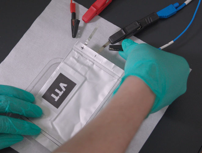
The cover is a thin plastic/aluminum film, and the cell can contain either single sheets of cathode, anode, and the separator (like in a coin cell), or a stack of several layers of electrodes and the separator. With more layers and bigger sheets, you can get higher capacity, but the assembly becomes more challenging.
Here a list of equipment that is needed for pouch cell assembly:
- Devices for slurry mixing, coating, calendering, and drying (as for coin cells but in larger scale)
- Cutters with different sizes
- Device for folding the separator (not mandatory)
- A welder for contacts
- Device for pouch cell forming (mandatory only for thicker multilayer cells)
- Heat/vacuum sealer
And the processing steps are the following:
Slurry mixing, coating, calendaring, and drying
All these steps are quite the same as for the coin cells. Everything needs to be done just in a bigger scale. Now it starts to be mandatory to use a roller press for calendaring as the area of electrodes is increasing. In an optimal case, coating should be done on both sides of the current collector if you are building multilayer cells.
However, it is possible to assemble single-side coated electrodes in a multilayer setup as well. It is not the way how it is done industrially but can be used for test cells. Coating is best done with a slot die coater instead of a doctor blade coater to get a straight edge, with the tab part left uncoated. I guess it is also possible to remove the coated electrode material from the tab area, but we have just left it uncoated as it is so easy with the slot die coater.
Cutting
Cutting can be again done with die cutters. Instead of circular cutters (used for coin cells), you need to order blades with the desired layout. The shape is rectangular for the blade to cut the separator. For the electrodes, you need a cutter having a layout, which also includes the contact tab. Die cutting can, and should, be done in a roll-to-roll process for longer rolls. But for building cells in a lab, manual cutting is sufficient.
Even though die cutting works quite well in lab scale, and can be up-scaled as well, more flexible methods regarding the design are looked for. This is when laser cutting can come to help as it is not restricted to a certain design. Laser cutting should be also better suited e.g., for Li metal cutting. Li metal is a soft and sticky material. Thus, normal die cutters are not optimal, especially in large scale. Lithium sticks easily on the blades and makes the process slow and difficult to handle. Li metal anode is often used in solid-state batteries instead of graphite. As Li metal batteries are becoming more and more mature and entering the market, upscaled cutting solutions for Li metal are needed.
Cell stacking
When assembling the cell, you need to stack different layers on top of each other. This means layering the anode + separator + cathode, like the slices of bread (anode & cathode) and cheese (separator) in a sandwich. Or, putting several stacks into one pouch cell to make a bigger battery, like a multilayer sandwich with more energy. The separator (the cheese slice) must be bigger than the electrodes (the slices of bread). Otherwise, the battery will be shorted.
It is also possible to fold the separator between the electrode sheets. This is called Z-folding. Note that if you are planning to use Z-folding of the separator, you of course do not need to cut it into a rectangular shape. I would anyway recommend cutting the separator and use it as separate sheets, as the folding is not very easy to get done perfectly. At least as far as I know, but we have never tested Z-folding in our lab.
Welding of the contacts
For making electrical connections, you need to weld the anode and cathode tabs into external nickel/aluminum connectors. An ultrasonic welder is used for this. We also tested a simpler spot welder, but the contact was not as good.
Pouch cell forming
Forming means that the pouch cell cover will be molded in a 3D shape. The idea is to make kind of a cup where the cell layers will fit in. For cells with only a few layers, the pouches do not need to be formed into any special shape. Thus, the forming device is not mandatory if you do not plan to assemble thick multilayer cells. However, for thicker cells, forming is needed. Otherwise, there will be wrinkles in the cell cover, which might lead to problems. It is also possible to buy formed pouch cell cases but then there is not much freedom for selecting the geometry. Thus, make sure that the cutters match with the size of available formed pouch cell cases if you are planning to use those.
Electrolyte filling and sealing of the cell
The sandwiched layers will be finally put into the aluminum coated polymer bag. These covers are sold as sheets or rolls. To start with, you need to put the battery stack on the cover, fold the cover, and heat seal the first two edges, leaving one side open. The half-ready cell needs to be transferred into the glovebox latest after this stage, and dried.
Next step is the electrolyte filling. This will be done by adding the electrolyte in the partly sealed bag with a pipette. The electrolyte must fill in the pores of the electrodes and the separator. If you are still thinking of the sandwich, you can image that you have there now mayonnaise that should soak the slices of bread and the cheese. So, you’d better use Emmental cheese, but with micron-sized holes instead of the big ones 😉 This also reveals the difference in manufacturing of conventional cells with a liquid electrolyte, and next generation cells with a solid electrolyte. If the mayonnaise has too high viscosity or does not flow at all, like the solid electrolyte, it won’t fill in the pores. Thus, solid state batteries require a different process for the electrolyte filling step. I’m planning to write about this topic in a later blog.
Anyway, once the electrolyte is in the cell, it is time to seal the final edge. This is done by vacuum sealing. You might want to leave some space for gas formation, which might happen during the first slow charging/discharging cycles, which are needed to create a stable interface on the electrode. If the cell is big and there is a lot of gas formation, another vacuum sealing should be done to remove the excess gas.
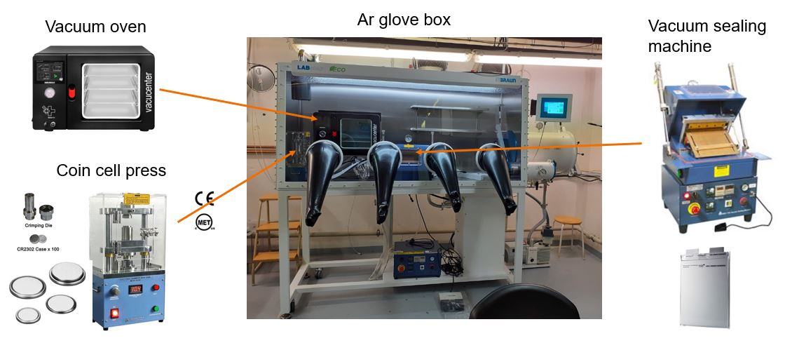
Currently, our glovebox setup looks like this
You can also find videos of the pouch cell process. We have also just made one, but I’m not able to publish it yet. I should be able to do this in a couple of weeks and will let you know when it is available! In the meanwhile, you can check for example this nice video by MTI: Pouch Cell Assembly Steps by MTI.